What is light?
Back to physicsSunlight reaches a wall, a mirror sends it in a new direction, and a closed curtain keeps most of it out. We can describe these observations without yet knowing what light is. That is our starting point. We want an explanation that tells us what will happen in another experiment, rather than a name that merely labels what we have already seen.
Does light take time to travel from one place to another? A measurement can help us answer. To understand what might be travelling, we can compare two things we can watch: a small object moving and a raised shape moving along a rope. We need to see what each piece of rope does for this comparison to be useful. Experiments with light will show where the comparison works and where it is not enough. We will explain each new term when we need it.
What anyone can observe
Let’s start with what you can see without any theory. A shadow has a sharp edge. Sunlight through a gap in a curtain makes a straight, bright shaft in dusty air. So light travels in straight lines, at least across a room. Light also carries energy: sunlight warms your skin, and a magnifying glass can gather enough of it to scorch paper.
Does light take time to arrive? For centuries many people thought it arrived instantly. In 1676 Ole Rømer was timing the eclipses of Io, a moon of Jupiter. He noticed that they came later than predicted when the Earth was on the far side of its orbit from Jupiter. They came earlier when the Earth was on the near side. The light from Io had to cross the extra distance, about the width of the Earth’s orbit: . Rømer estimated the extra delay as about 22 minutes. Dividing distance by time gives a speed:
That is enormous, but not infinite. (Today we know the extra delay is closer to 1000 seconds, about 17 minutes. So Rømer’s speed was too small by about a quarter. The important discovery was that there is a delay at all.)
In 1849 Hippolyte Fizeau measured the speed of light on the Earth. He used a distance he could check with surveying chains. Light from a lamp passed through a gap between two teeth at the edge of a spinning wheel. It travelled to a mirror on a hill and came back to the same edge of the wheel. If the wheel turned slowly, the light came back through the same gap, and the observer saw it. If the wheel turned fast enough, it moved on by half a gap-to-gap step during the light’s round trip. A tooth now stood where the gap had been. The returning light was blocked, and the observer saw darkness.
Try it below. The drawing is not to scale. The real mirror is much farther away, and the wheel has fewer teeth than Fizeau’s 720 so that you can see them. Change how fast the wheel turns. Watch whether the returning pulse meets a gap or a tooth.
- Round trip of the light
- Wheel turns during it
- gap-to-gap steps
The returning light passes through a gap: bright
Fizeau’s wheel had 720 teeth and 720 gaps. So one gap-to-gap step is of a turn, and half a step is of a turn. The first darkness came at 12.6 turns per second. At that rate, the time to turn of a turn equals the light’s round-trip time:
The light covered in that time. Modern measurements give , so Fizeau was within 5 per cent. We will write this speed of light as .
Fizeau’s wheel had 720 teeth. Suppose the mirror were twice as far away. At what speed would the first darkness appear?
Particles or waves?
Knowing how fast light goes still does not tell us what it is. Around 1700 there were two pictures. Isaac Newton favoured particles, which he called corpuscles. A stream of tiny bullets would travel in straight lines, cast sharp shadows and bounce off mirrors like balls off a wall. Christiaan Huygens favoured waves spreading through some material, as sound spreads through air. He explained why light bends when it enters glass or water: the wave slows down there.
Straight paths alone cannot settle this question: more than one model can explain them. We need an observation for which the models make different predictions. Two streams of ordinary pellets do not leave an empty patch just by meeting. But two disturbances on a rope can momentarily leave a piece of rope at its resting height. Understanding this cancellation will give us a way to test light. This comparison uses ordinary pellets; later experiments will show why a photon cannot be treated as a tiny classical pellet.
What a wave is
Imagine holding one end of a long rope and lifting it once. The part beside your hand rises, pulling the next part upward, and the raised shape travels away. Now keep moving your hand up and down. Below, five labelled beads mark five fixed places along the rope. Pause the motion and follow bead C. When you resume, C rises and falls along its own guide; it does not follow the raised shape to the right. A, B, D and E do the same at different times. The disturbance travels, although each marked piece stays near its own place. A travelling disturbance through a material is called a mechanical wave. This does not yet tell us whether light needs a rope, water or another material.
Watch A, then B, then C. Their horizontal positions do not change. Follow a raised part instead: it passes one bead after another. The animation runs at one quarter speed so these are two separate, visible observations.
To read the numbers: frequency counts complete cycles per second; period is the time for one complete cycle; wavelength is the distance between neighbouring crests. The speed below is the forward speed of the shape, not a bead’s vertical speed.
- Frequency
- Time for one cycle
- Crest-to-crest distance
- Pattern travel speed
We need two different measurements, because “how often one bead moves” and “how far apart two raised parts are” are different questions. Follow C from its highest point until it next reaches its highest point in the same way. That is one complete cycle. Its duration is the period, written T, measured in seconds. If C completes two cycles in one second, each takes half a second. The number of cycles per second is the frequency f; its unit is hertz, written Hz. Thus . Now pause the whole rope. A highest point of the shape is a crest. Measure from one crest to the next: this distance is the wavelength, written with the Greek letter , read “lambda”. The period measures time at one place; the wavelength measures distance across the shape.
We can now connect those measurements. At an instant when C is at the top, mark the crest above C. One period later, C has finished a cycle and another crest has reached C. Meanwhile the marked crest has moved to the next matching crest position, one wavelength farther right. So, in time T, the shape travels distance . Speed means distance travelled per unit time. Dividing by T gives the speed v of the travelling pattern; replacing 1/T by f gives the last expression below. This is not the up-and-down speed of a bead.
Select two cycles per second. The period is half a second and the crests are 1.5 metres apart, so the pattern travels metres per second. Increase the frequency. More crests must pass a place each second, so their spacing becomes smaller while the model keeps the same travel speed. For small waves on this ideal rope, that speed is set by its tension and mass per length. Other kinds of waves need their own rules: water-wave speed, for example, can depend on wavelength and depth. The material that carries a mechanical wave is called its medium. A rope wave needs a rope; sound can travel through air, water or solids, but not through a vacuum.
A wave on a rope has frequency and travels at . What is its wavelength?
When two waves meet
What does one piece of rope do when two disturbances reach it together? The two faint curves below show what each pulse would do on its own. The solid curve shows the rope when both are present. At the marked place, displacement means height above or below the resting line: upward is positive and downward is negative. In this small-displacement model, adding the two separate heights gives the actual height. For example, +1 and −1 give 0. That piece is at its resting height for that moment; the disturbances and their energy have not disappeared. The pulses separate again after meeting. This addition rule is called superposition. Pause where the pulses overlap and compare all three heights. When you resume, watch them pass through one another.
Compare the middle bead C with the two reference curves at that same place. Heights below are measured in units of one pulse’s peak height, upward positive and downward negative. A zero total means this place is at resting height at this instant.
Continue past the overlap: the pulses separate. Momentary cancellation is not the disappearance of the waves or their energy.
A rope gives us one line of places to inspect. On a water surface we can inspect places in a whole area. The two source pins below move together, making equal waves that spread out. The marked probe is one chosen place on the water, not a third source. We want to know why this place moves strongly while another hardly moves. Start with the equal-path position. Follow the two drawn routes from the sources to the probe, and then compare the two arrival indicators and their sum. Move to the half-wave-extra position and compare again. The surface model neglects weakening with distance so that the timing difference is the only cause of the change.
Drag the gold point to choose a place in the water. Orange is the route from source 1; blue is the route from source 2. Short ticks along each route are one wavelength apart. They count distance, not separate particles.
- Route from source 1
- Route from source 2
- Extra route
Read all three at the same instant. Upward is positive, downward negative, and one source alone has peak height 1. The right indicator is their sum; its larger range also allows 1 + 1 = 2.
Matching arrivals reinforce each other.
Now name the distances we have just compared. Write r₁ for the route from source 1, and r₂ for the route from source 2. The extra distance is . Both sources start together. If the routes are equal, matching parts arrive together. An extra whole wavelength also brings a matching part: crest still meets crest. An extra half wavelength brings opposite parts: when one arrival is at a crest, the other is at a trough. Their equal and opposite heights add to zero throughout the cycle. At other differences the result lies between these cases. This lasting pattern of reinforcement and cancellation is interference. The wavelength marks along the routes make the distance comparison visible; the indicators show why it changes the result.
Two sources send out waves in step with wavelength . At a point from one source and from the other, what happens?
Light interferes
We can now ask light the same question. In a double-slit experiment, light from the same source reaches two narrow openings. A screen beyond the openings records where light arrives strongly or weakly. On the screen there are alternating bright and dark bands, called fringes. At the middle of a dark fringe, either opening alone would illuminate the place, but with both open the light is cancelled there. A model of independent ordinary pellets does not predict this. The wave rule we just used does: arrivals with opposite oscillations can cancel. The apparatus below shows the openings and screen; the route diagram lets us inspect one point on that screen. This explains the interference pattern, not every property of light.
Keep the openings and screen fixed. We have just found that cancellation depends on the extra route compared with one wavelength. Therefore changing wavelength moves the places where cancellation occurs. Select red, green and violet below, and follow a dark band on the screen. Red gives wider spacing; violet gives closer spacing. Visible wavelengths are very short: roughly 400 to 700 nanometres, where one nanometre is one billionth of a metre. A green wavelength of 500 nanometres is 0.5 micrometres, or 0.0005 millimetres. In the route view the wavelengths are deliberately enlarged so we can count them. The screen view uses the double-slit geometry; its scale is labelled separately. The detailed calculation is in the double-slit lesson.
Choose a place on the screen by dragging the gold point vertically. The two routes are drawn far apart so we can see them; the real slit separation is only 0.15 mm. The lower strip shows the actual calculated screen brightness across 24 mm.
Screen: −12 mm to +12 mm. The white mark follows the selected place.
- Extra route compared with wavelength
- Screen brightness relative to a bright centre
- 100.0%
The indicators slow down the wave calculation; the screen does not contain moving water. To turn the signed sum into brightness, we need one additional rule: multiply each total by itself, then average these values over time. Multiplying a number by itself is called squaring. Positive and negative totals can both contribute brightness, but a total that stays zero produces darkness. This is the light-intensity rule used here; the field description comes later. We set the central bright fringe to 100% for comparison.
Matching arrivals reinforce each other.
Since light is a wave, holds for it too, with . For light of wavelength , the frequency is
Six hundred million million cycles every second. Whatever is waving in a light wave is waving extraordinarily fast.
Waves of what? The aether
Every wave we have met needs a medium. So what is the medium of light? A simple experiment shows the difficulty. Hang an electric bell inside a glass jar and pump the air out. As the air goes, the ringing fades to nothing, because sound needs air. But you can still see the bell perfectly well: light crosses the empty jar. And light from the Sun and the stars crosses the near-emptiness of space.
Orange rings: the sound of the bell · yellow lines: light from the lamp to the eye
Physicists of the 1800s concluded that all of space, even a vacuum, must be filled with an invisible medium whose vibrations are light. They called it the luminiferous aether, the “light-carrying aether”. Light would then travel at the speed relative to the aether, just as sound travels at relative to the air.
The rope has also shown a distinction we will need. Its pieces move up and down while the disturbance travels sideways: the motion is across the travel direction. This is called a transverse wave. Polarization experiments, which select an orientation of light’s oscillation, indicate that light is transverse too. A mechanical aether therefore needed a way to support transverse disturbances while allowing planets to move through it without the expected resistance. Giving that invisible material a name did not explain how it could have these properties. We should look for an experimentally testable account, rather than assume that every wave must be a shaking substance.
Why did the vacuum bell jar point to a problem for the wave theory of light?
Electric and magnetic fields
The rope comparison has left a question unanswered: if light can cross empty space, what can change where there is no material to shake? To reach another possibility, we first need two observations about electricity and magnetism. An object can carry positive or negative electric charge. Two like charges repel; unlike charges attract. To describe what a source charge would do at a chosen place, imagine putting a very small positive test charge there. Record the direction of its force and the force per unit test charge. We call this information the electric field at that place, written E. In the diagram, an arrow represents that information: direction shows the push on a positive test charge and length shows strength. The field is not literally an arrow. You can change the source sign below and watch the directions reverse. Coulomb’s law gives the quantitative distance rule, but remembering another page is not needed for this comparison.
Each arrow shows which way a small positive charge placed there would be pushed; longer arrows mean a stronger push
A compass gives us a different test. Near a magnet, its north-seeking end settles in a particular direction. The magnetic field, written B, records this directional magnetic influence and its strength. The field arrows indicate the direction of that north-seeking end. A wire carrying moving charges also affects a nearby compass. A flow of charge is called an electric current. So a magnetic field is associated not only with permanent magnets but also with currents. We now have two distinct measurements, E and B; their arrows need not point the same way.
Can a magnet make charges move through a wire? Connect a coil of wire into a closed circuit with a sensitive current meter. A coil is wire wound into repeated loops. Move the magnet towards its opening and hold it still there. While the magnetic field through the loops changes, an electric field drives charges round the circuit and the pointer moves. Holding the magnet still stops that change, and the pointer returns to zero. Pull it back and the pointer turns the other way. You can pause during the motion: the model sets the current to zero for the stationary magnet. The magnet enters the hollow coil, so we can compare being inside with moving inside. A changing magnetic field can produce an electric effect.
- Copper winding
- Bar magnet
- Zero-centre meter
Drag to inspect the apparatus, or use the view buttons. The lesson controls also change this view.
Push the magnet into the coil and hold it still inside. Compare the pointer while the magnet moves with the pointer while it is held still. Pulling the magnet out reverses the change. The pointer responds to how quickly the field through the loops changes, not just to whether a magnet is present.
Magnet held still: the pointer returns to zero.
This is a smooth qualitative field model, not a calibration of a particular magnet. The hollow coil, depth ordering and changing pointer all follow the same position and motion.
In the 1860s James Clerk Maxwell gathered all the known laws of electricity and magnetism. He noticed that something was missing. To make the laws agree with each other, he added one more effect. It is the mirror image of Faraday’s: a changing electric field creates a magnetic field, just as a current does. At the time this was only a prediction. The next chapter shows what followed from it.
A wave made of fields
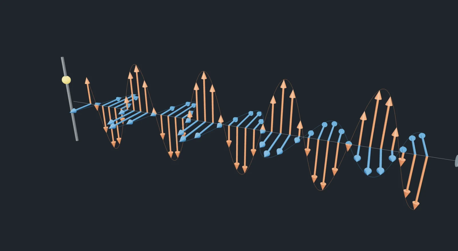
We now have a reason to consider the fields themselves. Changing magnetic fields are linked to circulating electric fields, and changing electric fields are linked to circulating magnetic fields. These are coupled laws: the spatial pattern and the change in time must agree with each other. Solving those laws allows a travelling pattern of E and B even in a region with no charges or material. This is an electromagnetic wave: “electro” refers to E and “magnetic” to B. The fields change together; one does not have to finish changing before it creates the other. An accelerating charge, such as charges driven back and forth in a transmitting antenna, can launch such a disturbance. This paragraph states a consequence of the field laws; the next chapter examines the speed that those laws require.
The model shows such a wave travelling to the right. The orange arrows are the electric field, and the blue arrows are the magnetic field. They are drawn at points along the line of travel. Notice three things. First, both fields rise and fall together, in step. Second, they are at right angles to each other and to the direction of travel. So the wave is transverse, just as Fresnel had found for light. Third, nothing material moves along: what travels is the pattern of the fields.
There is no single wavelength for this family of waves. We therefore need a map showing where a chosen wavelength belongs. The horizontal band below is that map, called the electromagnetic spectrum. Drag the marker on the band itself; the separate slider and arrow keys offer the same control. Each equal step on the labelled scale changes wavelength by a factor of ten, rather than adding the same number of metres. Moving towards longer wavelengths lowers frequency because their product remains c. The names radio, microwave, infrared, visible, ultraviolet, X-ray and gamma ray refer to regions of this family; the boundaries are approximate and some naming conventions overlap. Visible light occupies only a small part. The moving field model enlarges and slows the pattern; its drawn wavelength is a teaching scale, not a metre ruler for the chosen radiation.
Orange: electric field · blue: magnetic field · grey arrow: the direction of travel · drag to turn
- Kind of wave
- visible light
- Frequency
The model always draws a few wavelengths; the numbers give the real wavelength and frequency.
How fast the wave travels
The drawing shows a possible pattern, but a drawing cannot establish its speed. We need to ask what speed lets both field laws hold at the same time. Two constants appear in those laws: , read “epsilon zero”, sets the scale of electric effects in vacuum; , read “mu zero”, sets the scale of magnetic effects in vacuum. We do not derive the field laws here: they describe experimentally tested relationships. We will use a simple moving-front example to follow the algebra that connects them to the wave speed. First we must describe what each measurement in that example means.
In this ideal example, a boundary travels to the right at an unknown speed c. Behind it, E points up and B points out of the screen; ahead, both are zero. Use two imaginary square loops of side L as measuring frames, not as physical wires. For a uniform field perpendicular to a flat surface, field strength times area is called flux: it measures how much field crosses that chosen surface. We also need the sum of the field component along a complete loop, called its circulation. If only one side contributes and the field there is uniform and parallel to it, that sum is field strength times L. For E this circulation describes electrical work per charge; for B it is a magnetic-field measurement, not a mechanical pushing force. The two coloured loops below let us keep the two measurements separate.
Use loop 1 in the plane of the screen. In a short time Δt, meaning “a small time interval”, the front advances cΔt. It covers an extra strip with width cΔt and height L, hence area LcΔt. The magnetic field B crosses this strip perpendicularly, so magnetic flux increases by BLcΔt. Divide by Δt: its rate of increase is BLc. Faraday’s law equates the magnitude of electric circulation to this rate. Only the side behind the front contributes to that circulation, giving EL. Thus . Both sides contain the same nonzero length L, so we can divide by it. The directions are already chosen in the diagram; here we compare magnitudes.
Now turn to loop 2, perpendicular to the screen, so that E crosses its surface. The same strip argument gives an electric-flux increase per second of ELc. In a region without an electric current, the Maxwell–Ampère law says that the magnetic circulation equals times that rate. Only one edge contributes to the magnetic circulation, giving BL. We therefore get . Divide both sides by L again. This second relationship concerns the very same E, B and c as the first; that is why we can combine them.
We now have two results for the same wave. The second gives , so we can put that expression in place of in the first result. Dividing both sides by the nonzero wave amplitude gives:
Now put in the measured values. The units of and multiply to give , so the answer comes out in , as a speed should:
This is the speed of light. The two numbers came from experiments with charges, currents and magnets, and never mention light. Yet together they give exactly the speed Fizeau measured with his wheel. In 1865 Maxwell concluded that light is an electromagnetic wave. (Our calculation used only the sizes of the fields. The full equations also fix their directions, which the picture already assumed: , and the direction of travel are all at right angles to one another.)
In the derivation of the wave’s speed, what did Faraday’s law give for the front of the wave?
No aether to be found
If light is a wave of electric and magnetic fields, what carries these fields? Maxwell and almost everyone else assumed it was the aether. The fields would be a kind of strain in it, and would be the speed of light relative to the aether. The Earth goes round the Sun at about , so it must move through the aether. Then light measured on the Earth should travel slightly faster in some directions than in others. It is like a person walking on a moving wagon: seen from the platform, the walker’s speed depends on the wagon’s speed.
In 1887 Michelson and Morley compared light travelling out and back along two perpendicular paths. Recombining the light produces interference fringes, so a small change in the difference of travel times can shift those fringes. Rotating the apparatus did not produce the shift predicted by a stationary aether through which Earth was moving. This is called a null result: the expected signal was not found within the experiment’s sensitivity. It rejects that prediction; one experiment does not by itself settle every imaginable version of an aether. You can follow the path comparison step by step.
Einstein’s 1905 special relativity starts from a different set of principles. Observers moving steadily relative to one another use the same physical laws, and each measures the same vacuum light speed c. A special state of rest belonging to a mechanical light-carrying medium is no longer needed. Electric and magnetic fields can be described without treating them as strains of that substance. This gives us an answer to the question of chapter 6: a wave of fields does not require a rope-like material medium. It is a theory supported by experiments, not a deduction from the bell jar alone. We now need to test another part of the account: how light transfers energy to matter.
Light comes in lumps
We have used light to make patterns on a screen. Now use it to remove something from a surface. Metals contain electrons, very small particles carrying negative electric charge. Some electrons can move within a metal, but leaving its surface requires energy. Shine suitable light on a clean metal surface and some electrons escape. This is the photoelectric effect: light causes electrons to be emitted. In the apparatus below, light reaches a metal plate in an evacuated tube. A second piece of metal collects escaping electrons. Charge reaching the collector each second produces a current, so a current meter lets us detect their arrival.
To see why this is useful, consider a simple continuous-energy picture. Suppose each electron steadily collects energy delivered by the light wave until it has enough to leave. Increasing the intensity, meaning energy delivered to a fixed area each second, should then help an electron gather energy faster. Sufficient exposure might let even low-frequency light work; faint light should require a long energy-accumulation wait. These are predictions of this simple picture, not observations. We will compare them with ordinary low-intensity photoelectric experiments, where an emitted electron obtains the energy of one absorbed photon. Extremely intense light can produce additional processes outside this model.
The key observations disagree with that picture. At a fixed frequency above the metal’s threshold, increasing intensity raises the emission rate but not the maximum kinetic energy, meaning the largest energy of motion among the emitted electrons. Below the threshold frequency, single-photon emission does not occur. Nor is the long energy-accumulation delay predicted by the simple model observed. With very faint light, individual arrivals are still random: “no accumulation delay” does not mean that the first electron must appear at the instant a lamp is switched on. After building the explanation, use the apparatus to compare intensity, colour and metal while holding the other controls fixed.
Einstein’s explanation was that the energy of light is not spread smoothly through the wave but comes in lumps, later named photons. Each photon of light of frequency carries the energy
Here h is Planck’s constant, approximately . The joule, J, is a unit of energy; multiplying h by a frequency in cycles per second gives an energy in joules. In the single-photon model, an electron absorbs a photon’s energy in one event. It must use at least an energy W to escape the surface. W is called the work function; it depends on the surface and material. Any energy left over becomes kinetic energy. Some electrons lose more energy inside the metal, so this subtraction gives the maximum possible kinetic energy, written , rather than the energy of every emitted electron:
Keep the frequency fixed. A stronger beam now means more photons arriving each second, but the energy hf of each photon is unchanged. This can increase the emission rate without raising the maximum kinetic energy. If hf is smaller than W, one photon cannot supply enough energy for escape. The boundary occurs at , so is the threshold frequency. With , the corresponding longest wavelength is . The subscript zero labels this boundary. These statements use the single-photon model introduced above; they are not a claim that arbitrarily intense light has no other effects.
The energies are so small that joule values contain many zeros. We therefore introduce a smaller unit. Voltage measures the energy transferred per unit charge between two places. One volt, V, corresponds to one joule per coulomb; the coulomb, C, is a unit of charge. An electron has charge magnitude . Moving it through a one-volt potential difference in the accelerating direction transfers . That amount is one electronvolt, written eV: it is an energy, not a voltage. For a photon, substituting into gives . Converting this energy to electronvolts gives the useful relation below.
For example, a 450 nm blue photon has energy about . This model uses a representative sodium work function of ; a real surface’s value can vary. The maximum kinetic energy is therefore about . A 590 nm yellow photon has only about , below this model surface’s work function, so it cannot free an electron in the single-photon process. Compare the incoming energy with the required escape energy before looking at the meter.
We also need a way to measure the escaping electrons’ energy. Making the collector negative repels the negatively charged electrons. Let V be the size of this opposing voltage, so the energy lost on the way is eV, using the charge magnitude e defined above. An electron needs kinetic energy at least eV to reach the collector. Increase V until no electrons get through: the boundary is called the stopping voltage, . At this boundary . Because of the definition of an electronvolt, a maximum energy of 0.48 eV corresponds to a stopping voltage of 0.48 V. In the model, begin at zero reverse voltage; compare the two metals, then slowly increase the reverse voltage. The graph compares maximum kinetic energy with frequency, with one line for each model surface. The current scale is illustrative; its detailed decrease is not a measured current–voltage curve.
Coloured dots: photons · blue dots: electrons · the meter shows the current
- Frequency
- Photon energy
- Work function
- Fastest electrons
- Threshold
- Current (share of full scale)
Red light of shines on sodium (work function ). Making the light ten times brighter will
Wave and particle at once
We have two pieces of evidence to keep: interference depends on combining waves, and energy is exchanged in photon-sized events. Can an interference pattern still form when light is detected one event at a time? Use a source designed to send individual photons through a two-slit apparatus, and record each detection position. The simulation below draws separate detections using the interference pattern as their probability distribution; it is not a recording of experimental data.
Each ideal absorption happens at one place and adds one detection dot. The first few dots do not show a clear pattern. As more dots collect, some strips contain many and others contain very few. They line up with the bright and dark fringes we studied earlier. A low arrival rate lets you follow individual detections. Increase the rate while keeping the apparatus unchanged to compare how quickly the pattern appears. The rate changes how quickly we collect evidence, not where the fringes are. A small set of dots need not match the final distribution exactly.
Each dot is one photon arriving at the screen; the bars below count the dots at each place
Here is how physics describes this, as plainly as possible. The wave tells us where photons are likely to arrive. Where the wave pattern is bright, a photon is likely to land; where it is dark, a photon almost never lands. Each photon arrives whole, at one place, and gives up all its energy there. Neither picture alone is enough: light travels as a wave and arrives as photons. This double behaviour is called wave–particle duality. It turned out to be true of electrons and atoms as well. You can also build up the pattern from single detections.
In the faint-light two-slit experiment, what does each photon do?
Why the photon is not the aether
Both the aether and the photon are invisible, and both are “connected with light”. So it is natural to wonder whether the photon is just a modern name for the aether. It is not. They are different kinds of thing. The experiments in this lesson are exactly what showed the differences.
What it is. The aether was supposed to be a medium: a substance filling space, whose vibrations were light, just as the vibrations of air are sound. A photon is not something that light travels in. It is a piece of the light itself: the smallest amount of energy, , that light of frequency can deliver or take away.
A material aether was supposed to be a permanent background filling space. Photons are different: they can be emitted and absorbed in interactions with matter. A detector’s absorption ends that photon’s journey. Darkness to our eyes does not mean an absence of all photons: the warm walls of a closed box emit infrared radiation, which we cannot see. The distinction is between a proposed permanent material medium and radiation that can be produced, travel and be absorbed.
The proposed mechanical aether also supplied a preferred state of rest: a background against which all motion could be measured. The Michelson–Morley experiment did not find the directional effect predicted by the stationary-aether model. In special relativity, a photon in vacuum has speed c for every inertial observer, meaning an observer moving steadily without accelerating. There is no such observer travelling alongside the photon and seeing it at rest. Photons therefore cannot supply the stationary material background envisaged in that aether model.
Whether it can be counted. The aether was continuous, like a jelly. Photons come one at a time; you watched them arrive one by one in chapter 12.
| Property | The aether (abandoned) | The photon |
|---|---|---|
| What it is | a medium that light was supposed to be a vibration of | a piece of the light itself, energy |
| Does it last? | everywhere, always | created when emitted, gone when absorbed |
| Can it be at rest? | yes: it would define one special frame | no: always , in every frame |
| Can it be counted? | no: continuous | yes: one by one |
| Evidence | none found (Michelson and Morley, 1887) | photoelectric effect, single-photon detection |
The model below shows this difference in the simplest case. A wagon moves through the picture at speed . An observer on it measures how fast light pulses pass forwards and backwards. On the left, light is a wave in an aether that is at rest in the picture. Then the observer should measure ahead and behind, just as speeds add and subtract between moving viewpoints. On the right is what every experiment finds: both ways.
The yellow lamp on the wagon sends one pulse forwards and one backwards; speeds are enormously slowed down
We still use the word field, so it is reasonable to ask whether the electromagnetic field merely renames the old material aether. The crucial distinction is that the empty vacuum does not select a preferred inertial state of rest. A particular light beam, or a magnetic field produced by an apparatus, can have a direction and a relation to its source; that is not a universal material rest frame. In quantum theory, a photon is one excitation of the electromagnetic field. At a specified frequency f it carries energy hf. This connects the two descriptions without turning photons into the material of a mechanical medium.
What is the most important difference between the aether and the photon?
- 1676Rømer: light takes time to cross the Earth’s orbit
- 1690Huygens: light as a wave in a medium
- 1704Newton’s Opticks: light as particles
- 1801Young: two slits, interference fringes
- 1821Fresnel: light waves are transverse; the aether must be stiff
- 1831Faraday: a changing magnetic field makes an electric field
- 1849Fizeau: the speed of light measured on the Earth
- 1865Maxwell: light is an electromagnetic wave
- 1887Hertz makes radio waves; Michelson and Morley find no aether wind
- 1900Planck: the constant
- 1905Einstein: no aether; light comes in lumps (photons)
- 1909Taylor: interference with very faint light
- 1916Millikan confirms